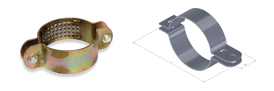
FIXPOINT CLAMPS
The fixpoint clamp (FPC) is made of steel with internal gripping teeth made of 316L stainless steel. The FPC is painted with a base paint that withstands welding.
The lower part of the clamp can be welded to the construction bridge (before installing the pipe) or it can be connected by screws. The distance between one adjacent pipe to the other is determined according to the width of the FPCs; see table “Dimension table of fixpoint clamps”.
Affix natural pipe bends with fixpoint clamps before and after each elbow. For pipe diameters of 280mm and larger, support the natural pipe bends in the center in addition to the two fix points noted.
Pexgol pipe behavior at high temperature
Pexgol pipes have a tendency to elongate considerably when exposed to sunlight due to a high thermal expansion coefficient which is typical for plastic pipes. With increasing temperatures, the elastic modulus of the pipe decreases so the developing stress is not high.
When placing Pexgol pipe over pipe bridges, the thermal expansion is reduced by the use of suitable fixtures so that the pipe will develop internal stresses which do not cause any damage. There is no need to use expansion joints!
Pexgol pipe behavior at low temperature
When the ambient temperature drops below 20°C, the tendency to axial contraction could create axial stresses in the pipe. These stresses are absorbed by the pipe without causing damage (stress relaxation). Minimum service temperature is -50°C.
Determining the maximum distance between two guiding clamps see Above-Ground Installation Guidelines.
Maximum force at the fixpoint clamps
Pipes in Above-ground installations are subjected to temperature variations which induce axial thermal movements: contraction or elongation.
These axial thermal movements are partially balanced by external friction between the pipe and the construction.
If a pipe is restrained with fixpoints, they will tend to restrain these thermal movements. As a result, these fixpoints will be subjected to axial forces which are balanced by axial thermal stresses inside the pipe’s wall.
The axial thermal stresses can be calculated by the following formula:
Sigma = E x A x ∆T where:
E is the relevant (short term or long term) Modulus of Elasticity.
A is the coefficient of thermal expansion or contraction.
∆T is the temperature difference.
The values of the Modulus of Elasticity and the values of the coefficient of thermal expansion or contraction are temperature dependent and so are the values of the axial thermal stresses.
Dimension table of fixpoint clamps
Cat. No. | Pipe Diameter (mm) | Length W (mm) | Width A (mm) | Weight (kg) |
---|---|---|---|---|
66206302 | 63 | 40 | 185 | 1.11 |
66207525 | 75 | 40 | 195 | 1.17 |
66209003 | 90 | 40 | 210 | 1.25 |
66211004 | 110 | 50 | 230 | 1.67 |
66212505 | 125 | 50 | 250 | 1.86 |
66214006 | 140 | 50 | 260 | 1.94 |
66216006 | 160 | 50 | 280 | 2.05 |
66218006 | 180 | 55 | 700 | 2.5 |
66220008 | 200 | 60 | 320 | 3.61 |
66222508 | 225 | 80 | 350 | 5.12 |
66225010 | 250 | 80 | 370 | 5.46 |
66228010 | 280 | 80 | 400 | 5.97 |
66231512 | 315 | 80 | 435 | 6.46 |
66235514 | 355 | 100 | 475 | 8.84 |
66240016 | 400 | 100 | 520 | 9.79 |
66245018 | 450 | 100 | 570 | 10.8 |
66250020 | 500 | 100 | 620 | 11.85 |
66263024 | 630 | 100 | 754 | 14.45 |

The highest values of the thermal stresses occur during the relatively short stage of temperature changes and therefore they involve the short term Modulus of Elasticity.
These initial Short term thermal stresses in the pipe decrease with time due to Stress relaxation. Theses Long term stresses are usually low and therefore they are of no concern for the Pexgol pipe itself. However, the initial high forces are transmitted through the Fixpoints to the metal construction and they can damage it.
Since the axial forces in the Fixpoints and the metal construction are equal to the axial thermal forces in the pipe, it is easier to calculate directly the axial thermal forces in the pipe.
The axial thermal forces in the pipe can be calculated by multiplying the thermal stresses by the pipe cross section.
It is recommended to design the metal construction based on the maximum theoretical axial forces. The values of maximum theoretical axial forces are calculated assuming that the friction forces between the pipe and the construction are negligible.
The worst case scenario is when the pipe is installed in a certain ambient temperature T1 and then the temperature is going down to a lower temperature T2.
As the temperature is going down, the tendency of the pipe to contract is balanced by tensile forces in the fixpoints.
The following table presents the values of the initial short term thermal stresses as a function of the design temperature.
Initial short term thermal stresses vs design temperature
Design Temp | Thermal Stress [MPa] | |
---|---|---|
Ti [C°] | Tf [C°] | |
100 | 110 | 0.25 |
90 | 100 | 0.26 |
80 | 90 | 0.28 |
70 | 80 | 0.29 |
60 | 70 | 0.31 |
50 | 60 | 0.36 |
40 | 50 | 0.41 |
30 | 40 | 0.53 |
20 | 30 | 0.65 |
10 | 20 | 0.66 |
0 | 10 | 0.88 |
-10 | 0 | 1.01 |
-20 | -10 | 1.3 |
-30 | -20 | 1.61 |
-40 | -30 | 2.72 |
-50 | -40 | 1.11 |
These values are valid for a temperature difference of 10°C.
The following calculation example illustrates the way to calculate the axial forces in the fixpoints.
A Pexgol pipe OD 280mm; wall thickness 25.4mm; SDR 11 was installed in an ambient temperature of 40°C.
The design temperature in this case is 40 + 20 = 60°C
In winter the temperature drops down to -30°C. The design temperature in this case is -30°C.
The axial forces in the fixpoints are calculated by adding the values of the thermal stresses for the temperature range between +60°C to -30°C, and then multiply them by the cross section of the pipe.
The sum of the values of the thermal stresses from the table “Initial short term thermal stresses vs design temperature” is 7.72 MPa:
Ti [C°] | Tf [C°] | Thermal Stress [MPa] |
---|---|---|
60 | 70 | 0.31 |
50 | 60 | 0.36 |
40 | 50 | 0.41 |
30 | 40 | 0.53 |
20 | 30 | 0.65 |
10 | 20 | 0.66 |
0 | 10 | 0.88 |
-10 | 0 | 1.01 |
-20 | -10 | 1.3 |
-30 | -20 | 1.61 |
Sum of the values: 7.72
The cross section of the pipe can be easily calculated from the Formula:
A= 3.14 x (D-T) x T
For OD 280mm wall thickness 25.4mm the pipe cross section is
3.14×254.6×25.4 = 20,306 mm2
The axial forces in the fixpoints:
20,306 x 7.72= 156762 N=15.67 ton
Side deflection
Large side deflection might be expected in the event of a malfunction, but there is no risk of possible damage due to one pipe “leaning” on its neighbor or rubbing against it.
Guiding camps for Pexgol pipes
The Pexgol pipe’s tendency to “snake” is reduced by putting bars on both sides of the pipe to limit sideward deflection. Alternatively, using guiding clamps (GC), which are conventional clamps (FPC) without the internal gripping teeth, is recommended. The pipe can freely slide through in the axial direction but not sideward.